01 Why Isaac Sim
Where a 3DGS scan should go depends on what you're using it for. For film and video work, UE5 gives you the most freedom. But if the goal is robotics, autonomous mobility, or sensor simulation, NVIDIA Isaac Sim is the obvious choice — because it lets you turn a real location directly into a validation environment.
- Run robots through a real place — instead of a fictional space, the simulation environment can be the actual site you scanned.
- Coexists with physics simulation — PhysX rigid bodies, joints, and sensors can operate inside a photoreal, scan-based background.
- Mass-produce training images — camera images can be generated at any angle against a real-world backdrop.
Isaac Sim 6.0 renders Gaussian splats natively. Because they participate in RTX path tracing, depth of field and motion blur work on them out of the box. That said, bringing real data in surfaces a few walls that aren't documented anywhere.
02 What you'll need
- Isaac Sim
- 6.0 or later. It unpacks to a large install, so leave plenty of free disk space
- Scan data
- 3DGS
.ply - Conversion tool
- PlayCanvas splat-transform (npm, free)
- USD conversion
- Bundled with Isaac Sim by default — no extra install needed
Avoid installing to C:\Program Files. The tool writes data while running, and placing it somewhere that requires administrator privileges invites unnecessary trouble.
.ply, splat-transform reads the proprietary formats of most major scanners and viewers directly. That saves the step of dropping to an intermediate format — and those packages often ship with a collision mesh and the camera trajectory captured during the scan, both of which pay off later in the pipeline. If you have the original format on hand, starting from it is worth it.03 First hurdle: exceed the draw-count limit and nothing renders
If you're working with a sizeable scan, get this straight first.
What makes this nasty is that every step upstream reports success. The file is written correctly and lands on the stage correctly. Only the rendering fails.
This limit isn't documented anywhere official. The only clue is a single line buried in the log: Failed to create TLAS. The fix is either reduce the point count or split into multiple prims — this article covers the former.
Failed to create TLAS before anything else. Checking this first is the reliable way to avoid misdiagnosing a black screen as a camera problem.04 Import steps
Bring the point count under the limit
Pass a target point count to splat-transform's --decimate.
# Specify an absolute count (keep it under 2^24 = 16,777,216)
splat-transform input.ply -d 16500000 output.ply

# A percentage also works
splat-transform input.ply -d 95% output.ply
This isn't random deletion — it merges nearby Gaussians together. Trim only a little and the visual degradation is barely noticeable.
Convert to USD and place it on the stage
From Python inside Isaac Sim, use the bundled converter to turn the PLY into USD. Give the output the .usdc extension. Using .usdz stores the contents as text and bloats the file size.
Before referencing the new data, clean up any existing Gaussian splats on the stage. Leftover old data makes it look like "only part of the new scene is showing," which makes tracking down the actual cause needlessly hard.
from omni.kit.converter.gsplat import convertPlyUSD
convertPlyUSD(r"output.ply", r"scene.usdc")

import omni.usd
stage = omni.usd.get_context().get_stage()

# Remove any existing Gaussian splat prims
for p in list(stage.Traverse()):
    if p.GetTypeName() == "ParticleField3DGaussianSplat":
        stage.RemovePrim(p.GetPath())

# Reference without specifying a type — use OverridePrim
prim = stage.OverridePrim("/World/Scene")
prim.GetReferences().AddReference(r"scene.usdc")OverridePrim, which leaves the type unspecified.Fix the upside-down orientation
The converter lets you specify the up axis, but converting Z-up scan data with the Y-up setting flips it upside down — buildings end up hanging downward from the ground.
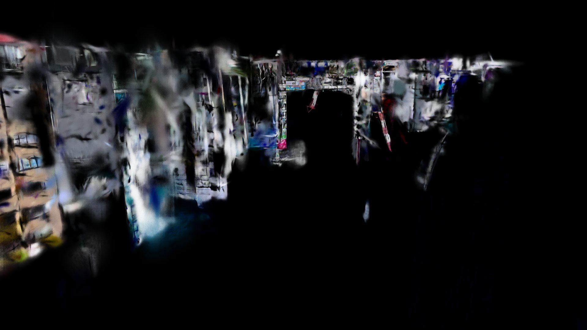
If you miss this and place the camera expecting to be "looking down from above," you're actually looking at the underside of the ground, and the screen comes out black. Applying a −90-degree rotation around the X axis to the prim restores the original orientation.
from pxr import UsdGeom

x = UsdGeom.Xformable(prim)
x.ClearXformOpOrder()
x.AddRotateXOp().Set(-90.0)
05 Placing the camera
The practical trick is not to compute the camera position yourself. Auto-computing a distance from the bounding box doesn't work — it gets dragged around by sparse outliers. Scan data scatters stray points well outside the actual captured area, so the overall extent comes out far larger than the region you actually want to look at.
Instead, use coordinates from the trajectory actually walked during the scan. Most scanners output the movement path as pose data — pick a point on it, place the camera at eye height (around 1.7m), and point it horizontally.
The reason to use the trajectory is simple: wherever the person doing the scan actually walked is where the data is recorded at the highest density. Put the camera outside the captured area, and you're looking at surfaces that were never scanned in the first place. If you don't have pose data on hand, the reliable approach is to start close in, do test renders, and pull back while watching what's actually captured.

06 Weaknesses for industrial simulation
This is where it gets interesting. 3DGS is unbeatable on "how it looks," but it carries almost none of the information industrial simulation actually needs. Here's what turns up when you actually pull outputs from Isaac Sim and check them.
Weakness 1: the whole scene is a single lump — no per-object separation
This is the biggest constraint. A 3DGS scene is one prim holding an enormous number of Gaussians, with no concept of "this building," "that traffic light," or "that car." You can't select object A separately from object B the way you would with 3D models, and you can't move, hide, or swap out a specific object on its own.
Simulation typically assumes operations like "move just the target object" or "swap out an obstacle" — and a 3DGS scan, as scanned, can't do that.
Weakness 2: only one semantic label per scene
Isaac Sim can output semantic segmentation — images classified pixel by pixel as "this is road," "this is a building," and so on — which is central to generating training data for perception AI. Gaussian splats can be assigned labels, and they do show up in the segmentation output.
But the unit a label attaches to is the prim. Since the whole scene is one prim (Weakness 1), the label that ends up applied is also just one, for the entire scene. Pull the actual output and buildings, roads, sidewalks, and traffic lights all come back painted with the same ID. For uses like "train only on the road region" or "extract just the signage," this doesn't work as-is.
Weakness 3: no physical collision
Gaussian splats are appearance data — they carry no surface information. As a result, they can't participate in the physics engine's collision detection. A robot passes straight through walls and falls through the floor. There's a floor to look at, but physically, there's nothing there.
Weakness 4: lighting can't be changed afterward
3DGS bakes the light present at capture time directly into the color data. Scan data captured under an overcast sky stays overcast even if you add sunlight to the scene. If you need training data varied across time of day or weather, this property becomes a real constraint.
07 Working around the weaknesses
Every one of these has a workaround. The shared idea is a division of labor: "3DGS handles appearance, a mesh handles everything else." This is also the architecture NVIDIA itself points toward.
Fix 1: pair it with a collision mesh (physics)
Overlay a simplified proxy mesh at the same position as the 3DGS data, and assign collision to that instead. The splat handles appearance, the mesh handles collision, and the mesh itself stays hidden.
from pxr import UsdPhysics, UsdGeom

mesh = stage.GetPrimAtPath("/World/CollisionMesh")
UsdPhysics.CollisionAPI.Apply(mesh)          # Add collision
UsdGeom.Imageable(mesh).MakeInvisible()      # Hide the appearance
There are three ways to get the mesh. Using a mesh the scanner already produced alongside the scan is the easiest. Failing that, splat-transform can generate a collision mesh directly from the 3DGS data. Or approximate the floor, walls, and obstacles with simple boxes — if the question is just "can the robot get through here," boxes are often enough.
Fix 2: split by region and label each piece (semantics)
If labels attach at the prim level, splitting the prim splits the labels. Cut the splat data up spatially, write each piece out as a separate USD, and assign labels individually.
Do the splitting before bringing the data into Isaac Sim — select regions in SuperSplat (PlayCanvas's free editor) and export them individually, or slice mechanically by coordinates. That said, effort scales with how finely you split. A coarse split like "road / building / everything else" is realistic; manually labeling at the level of individual objects isn't practical.
Fix 3: accept the lighting limitation, or use a different tool
Relighting the 3DGS data itself is outside what Isaac Sim can do. If you need variation across weather or time of day, either run the rendered output back through image-generation AI afterward, or capture the scan multiple times under different conditions. UE5 has plugins that support relighting, so building assets there is another option.
Knowing where it fits
Put all of this together, and the use cases where 3DGS shines and where it doesn't split fairly cleanly.
| Use case | 3DGS alone | Notes |
|---|---|---|
| Photoreal backgrounds / visual validation | ◎ | Its biggest strength — reproduces a real location as-is |
| Generating camera images (as background) | ○ | Any angle works, but there's no pixel-level ground-truth label |
| Robot movement / collision testing | ✕ | Requires a collision mesh alongside it |
| Segmentation training data | ✕ | Requires a labeled mesh layered on top |
| Per-object manipulation / swapping | ✕ | Only possible after splitting; pairing with CG assets is faster |
| Lighting variation | ✕ | Baked in — needs a separate method |
Put simply: 3DGS is a technique for bringing a real environment in as a photoreal background. Whatever moves within it, and whatever needs ground-truth labels, still gets built the traditional way, with meshes. Get that division of labor right, and 3DGS becomes an extremely strong option.
08 Summary
The import path is a straight line: "decimate under 224 points → convert to .usdc → reference with OverridePrim → fix the orientation → place the camera on the trajectory." The trip-ups cluster at the two ends — go over the point limit and nothing renders, with no error, and place the camera outside the scan area and all you see are broken surfaces. Get those two right and the rest goes smoothly.
For industrial use, the fastest way to think about it is that 3DGS is a technique for bringing a real environment in as a photoreal background — nothing more, nothing less. Per-object separation, semantic labels, and collision detection are all things the splat itself doesn't carry. When you need them, layer a mesh on top and split the responsibilities. The flip side is that fidelity of appearance is something no other method really replaces.
Splitting the work between this and UE5 depending on the use case is also realistic. Output aimed at film and video is covered in the UE5 × XGRIDs SDK article. If anything about using 3DGS is on your mind, feel free to reach out.
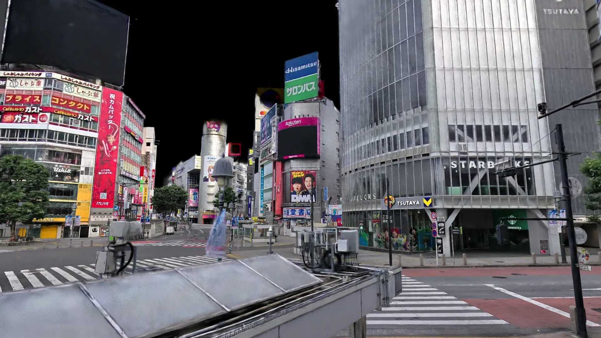
The Shibuya scramble crossing 3DGS data used in this article is available to purchase and browse
on Locahun 3D's online platform
Provided as PLY / OBJ (with a 3DGS walkthrough). Standard license from ¥200,000 (commercial and non-commercial use permitted). If you'd like to try this same Isaac Sim workflow yourself, take a look.
View the property data →